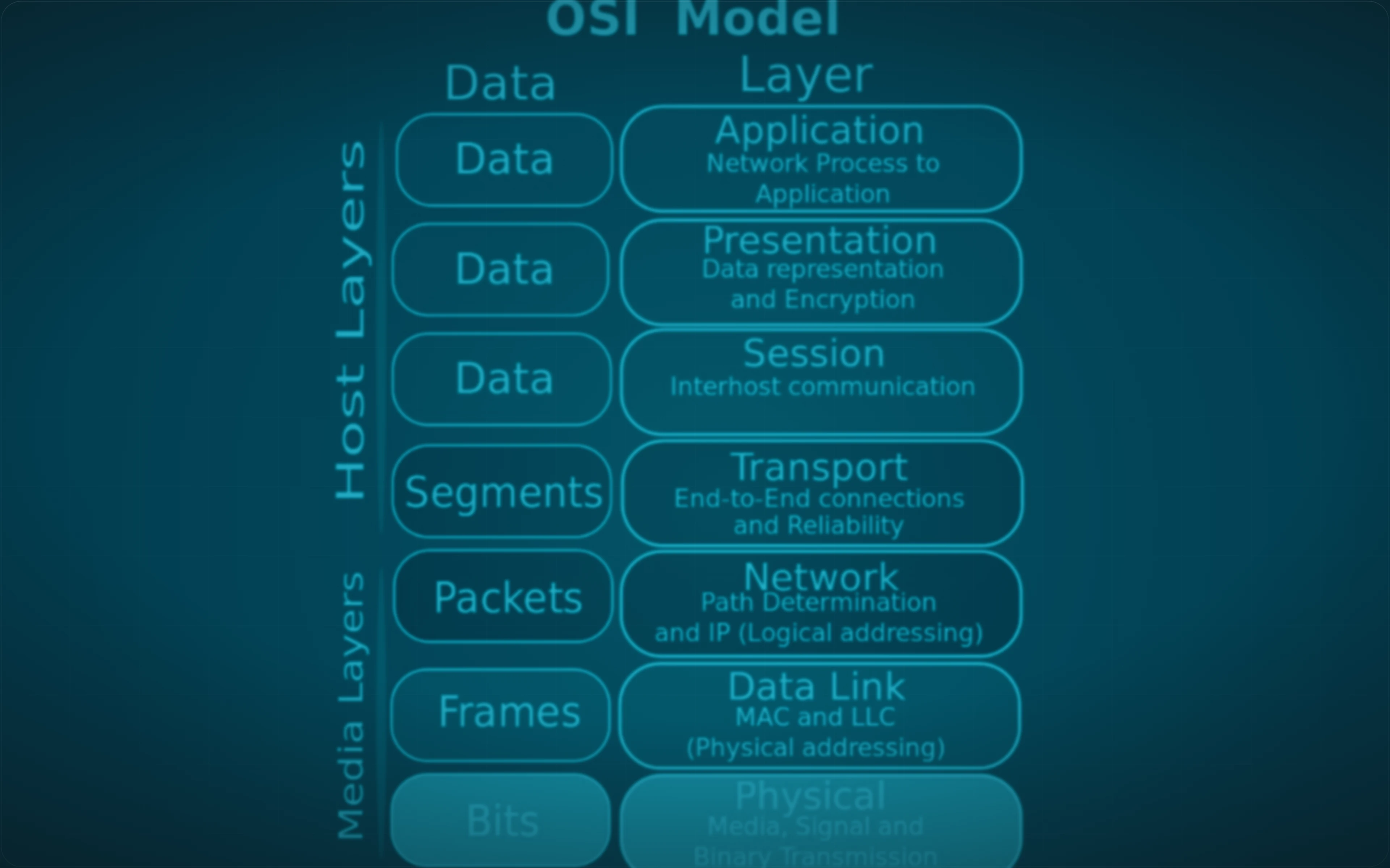
An Ethernet frame is the unit of data at layer 2 of the Open Systems Interconnection (OSI) model, the data link layer. It is what actually travels between two devices on the same local link, and everything above layer 2 rides inside it as payload.
A switch has no idea what a web page is, what a file transfer is, or which network a packet is ultimately headed for. It reads twelve bytes at the front of every frame, looks one of them up in a table, and picks a port. That is the whole job, and doing it in hardware a few million times a second is why the star topology beat everything else.
The fields of an Ethernet frame
A frame is built by the sender, read by each switch along the way, and destroyed and rebuilt at every router it crosses. That makes a frame local: it does not survive a hop between networks, and neither do the addresses in it.
The four fields that matter for understanding switching:
| Field | Size | What it holds |
|---|---|---|
| Destination MAC address | 6 bytes | The interface the frame is for, on this link |
| Source MAC address | 6 bytes | The interface that sent it |
| Payload | Variable | What is being carried, normally an IP packet |
| Frame check sequence | 4 bytes | A checksum over the frame, for detecting corruption |
A real frame has more than this: a preamble and start-of-frame delimiter that let the receiver's clock lock on, and an EtherType field saying what the payload is, so the receiver knows to hand it to IP rather than something else. Those four are where the behaviour lives.
One frame, read byte by byte
A real frame is that table with values in it, and reading one is easier than reading a description of one. The capture opened below comes from the lab in "Watching a switch learn", where three hosts share a bridge, one host sends frames with their addresses set by hand, and a third host captures everything that reaches its port.
wireshark -r out/switching-hostc.pcapngTwo frames reached that port over the whole run, and the host that received them was the destination of neither.
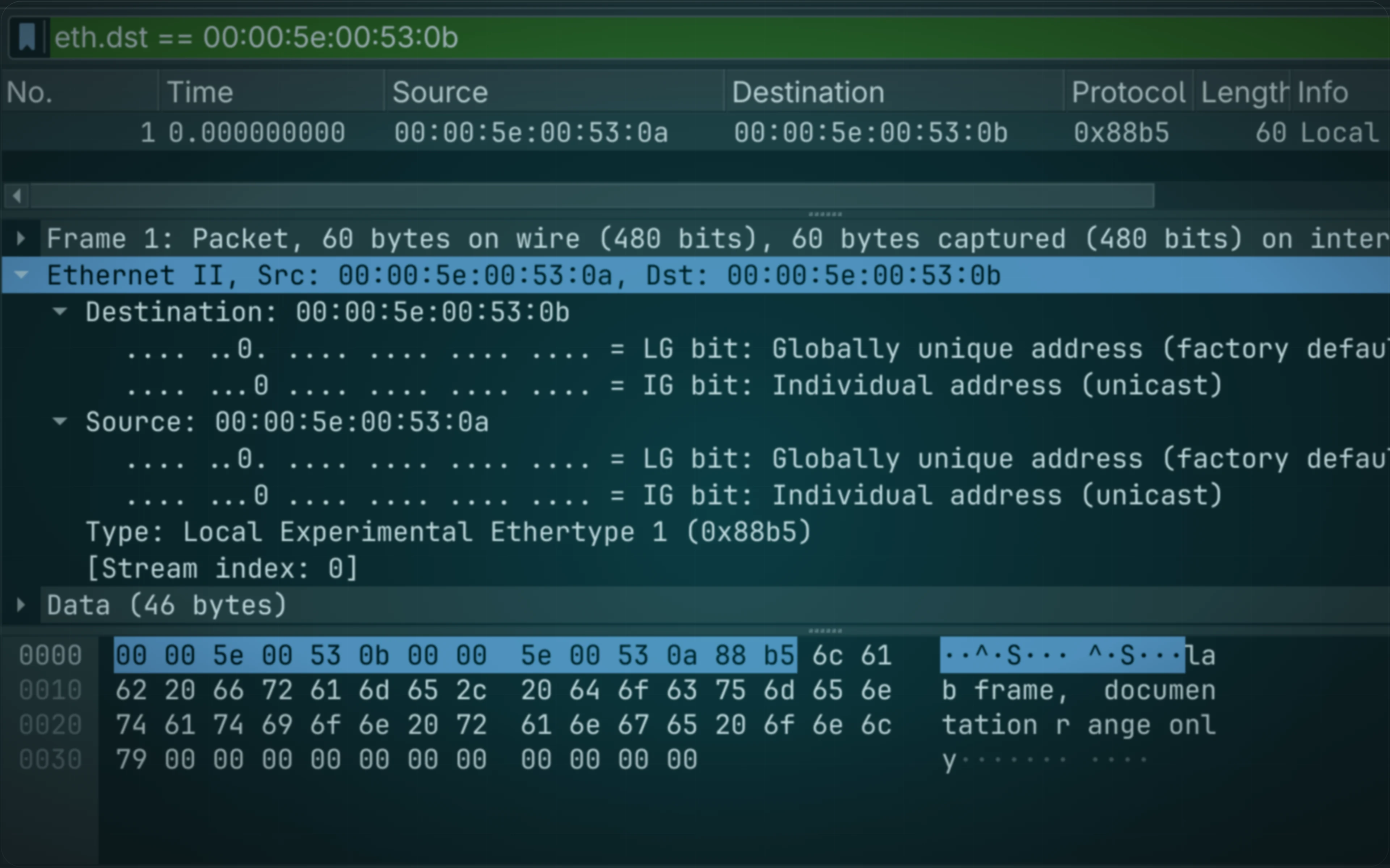
Typing eth.dst == 00:00:5e:00:53:0b into the filter bar picks out the first: the frame host A addressed to host B.
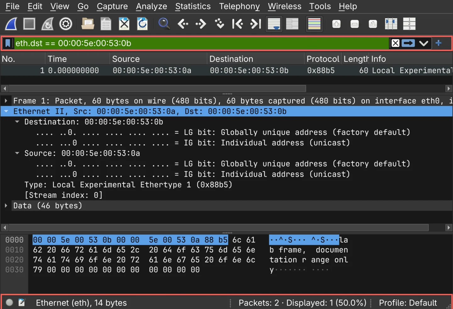
Selecting the Ethernet II layer highlights the fourteen bytes it owns, and those fourteen bytes are the entire header a switch reads before it decides where the frame goes.
The dump at the foot is the frame itself, and it runs in the order the fields were listed:
| Offset | Bytes | Field |
|---|---|---|
0000 | 00 00 5e 00 53 0b | Destination address, host B |
0006 | 00 00 5e 00 53 0a | Source address, host A |
000c | 88 b5 | EtherType, here the value reserved for local experiments |
000e | 6c 61 62 20 66 72 61 6d 65 … | Payload, the text lab frame, documentation range only |
0031 | 00 00 … | Padding, up to the 46-byte minimum payload |
Three things in that dump are worth stopping on.
The two flag bits under each address are the first byte, read bit by bit.
LG says whether the address is the one the manufacturer assigned or one set locally, and IG says whether it addresses a single interface or a group.
Both are zero here, which is what makes these unicast addresses; the broadcast frame further down has the group bit set, and every bit besides.
The padding exists because Ethernet sets a minimum frame size, and a short payload has to be filled out to reach it. This sender padded explicitly; a network stack does the same thing for you.
And the frame check sequence is not there. Sixty bytes are captured, which is fourteen bytes of header and forty-six of payload with no room left for a four-byte checksum. The adapter checked it and stripped it before the operating system ever saw the frame, which is why a capture almost never shows one - the field exists on the wire, and by the time anything can read the frame, its only remaining effect is whether the frame arrived at all.
Destination and source MAC addresses
A media access control (MAC) address is a 48-bit identifier belonging to a network interface, normally written as six hexadecimal pairs such as aa:bb:cc:dd:ee:ff.
The destination MAC address says which interface on this link should receive the frame. It is the field a switch looks up to decide where to send it.
The source MAC address says which interface sent it. The sender is not being polite: this field is how every switch on the path learns where that device is, which is the next section.
One special value matters throughout the rest of this post.
ff:ff:ff:ff:ff:ff is the broadcast address, and a frame sent to it is intended for every device on the local network.
The payload
The payload is the data the frame is carrying, which in almost every case is an IP packet with its own header and its own addresses.
This is where the two addressing systems sit on top of each other. The frame is addressed to a MAC address that means something only on this link; inside it, the packet is addressed to an IP address that means something across the whole internet. A router opens the frame, reads the packet's destination, and builds a completely new frame for the next link, with new MAC addresses and the same packet inside.
The frame check sequence
The frame check sequence (FCS) is a 4-byte field at the end of the frame holding a cyclic redundancy check (CRC) calculated over the frame's contents. The sender computes it over the frame it is about to put on the wire; the receiver computes the same value over what actually arrived, and compares the two.
What happens on a mismatch is the part worth knowing. The frame is discarded, and that is the whole of Ethernet's response to corruption: no correction, no retransmission, no word back to the sender. Recovering the lost data is TCP's job several layers up, which is one reason a link with a physical fault shows up as slow rather than as broken.
There is no figure of a failed check on this page, and this lab cannot produce one. Its hosts are joined by virtual interface pairs inside a namespace, so there is no cable, no connector and no interference: nothing in the path is capable of corrupting a frame. A real failure would leave nothing to capture either, for the reason the dump further up already showed - the adapter verifies the FCS and strips it before the operating system sees the frame, and a frame that fails is dropped there rather than handed up to anything that could record it.
So the only place a failed check is visible is the receiving interface's own counters:
ip -s link show eth0The errors figure under RX is where it lands, together with the other reasons a frame can arrive unusable; a driver that keeps a finer breakdown exposes it separately as rx_crc_errors under ethtool -S.
A count that climbs there while traffic flows is a physical-layer fault - a damaged cable, a loose connector, a run past its length limit - and no amount of packet capture will explain it, because the frames it is counting never became packets.
How a switch learns: the MAC address table
A switch keeps a table mapping MAC addresses to the port each one was last seen on. It is called the MAC address table, or the content addressable memory (CAM) table after the hardware it is stored in.
| MAC address | Port |
|---|---|
aa:aa:aa:aa:aa:aa | 1 |
bb:bb:bb:bb:bb:bb | 2 |
cc:cc:cc:cc:cc:cc | 3 |
A switch starts with this table empty and fills it by watching traffic. When a frame arrives, the switch reads its source MAC address and records that this address is reachable through the port the frame arrived on.
That is all the learning there is. No configuration, no announcement, no protocol: a device that sends anything at all has told every switch between it and the destination where it lives.
Entries age out, typically after five minutes of silence, so a device that is unplugged and moved to another port is relearned rather than permanently wrong.
Forwarding a known destination
Once the table has an entry, forwarding is a lookup.
The switch reads the frame's destination MAC address, finds it in the table, and sends the frame out that one port and no others. Every other port sees nothing.
This is the difference between a switch and the hub it replaced. A hub repeated every signal to every port, so every device saw every frame and one conversation used the whole segment's capacity. A switch gives each conversation its own path, which is why several pairs of devices can talk simultaneously at full speed.
It is also the reason packet capture on a switched network sees so little: your interface is handed the frames addressed to it, and the switch never sends you anyone else's.
Flooding an unknown destination
When the destination MAC address is not in the table, the switch cannot know which port to use. It does the only thing that works: it sends the frame out of every port except the one it arrived on. This is flooding.
It is not a failure. It is how the first frame to a device that has not spoken yet gets delivered, and the reply teaches the switch where that device is, so the second frame is forwarded normally.
Broadcast frames, addressed to ff:ff:ff:ff:ff:ff, are flooded too, and always: there is no port that would satisfy "everyone".
The three behaviours in one line each:
| The switch reads | And does |
|---|---|
| Source MAC address | Learns which port this device is on |
| Destination MAC address, known | Forwards out that one port |
| Destination MAC address, unknown | Floods out every other port |
| Destination MAC address, broadcast | Floods out every other port |
Watching a switch learn
The lab for this is three hosts plugged into one Linux bridge, built inside an unprivileged namespace, with every hardware address taken from the block RFC 7042 reserves for documentation. Host C is the control: it never sends anything and is never addressed, and the only question asked of it is whether traffic between the other two arrives at its port anyway.
Ping cannot answer that question, because the address resolution it does first teaches the bridge both hosts before the first unicast frame exists. So host A sends one frame directly, with the addresses set by hand.
Inside host C, a capture runs from before the first frame to after the last, filtered to the one EtherType these frames carry so nothing else the kernel sends can get into it:
dumpcap -i eth0 -f "ether proto 0x88b5" -w out/switching-hostc.pcapngThat is the file both Wireshark figures on this page were opened from. Running the lab starts it, sends the frames, and stops it:
./switch.sh
Read it in order. The table starts empty, because a switch is born knowing nothing. Host A sends one frame addressed to host B, and host C receives it - a frame that has nothing to do with host C, delivered to host C, because the switch did not know where host B was and flooding is what it does about that.
The table then holds host A and only host A. The switch learned the sender from the source address of that frame, exactly as described above, and learned nothing about the destination, because nothing in the frame says where host B is.
Host B then sends one frame of its own, which is all it takes: the table now holds both. The identical frame from host A goes out again, and this time host C receives zero.
The third run is the row of the table that learning cannot touch.
Host A sends one frame to ff:ff:ff:ff:ff:ff while the table holds both hosts, and host C receives it anyway - not because the switch is ignorant, but because a broadcast asks for every port and there is no single port that satisfies that.
A switch cannot learn its way out of a broadcast, which is why the size of a broadcast domain is a number worth knowing.
That broadcast is the second of the two frames in the capture, and swapping the filter for eth.dst == ff:ff:ff:ff:ff:ff brings it up on its own.
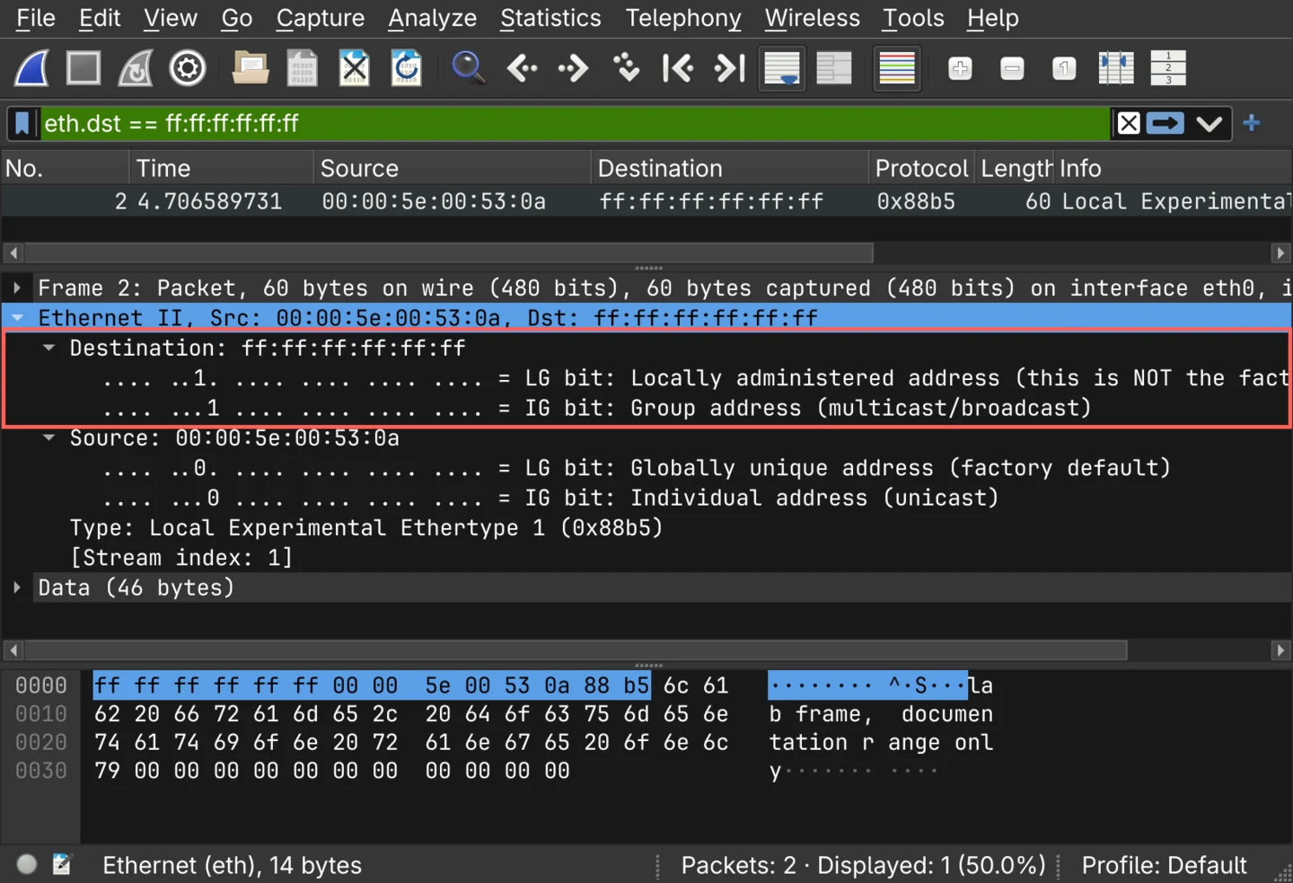
Both flag bits are set, because every bit in the address is.
LG says the address was not assigned by any manufacturer, which is true: no interface has this one.
IG says it is a group address rather than an individual one, and that is the bit doing the work - it is how an interface tells an address meant for a single interface from an address meant for a set of them.
This particular value is the set that means all of them.
That gap between the first two runs is worth holding on to. An unknown destination is delivered to every port on the switch, and a known one is delivered to a single port. It is also the condition a MAC flooding attack sets out to create: fill the table with invented source addresses until there is no room left to learn a real one, and every unicast frame on the switch is flooded to the attacker's port for as long as the table stays full.
Collision domains
A collision domain is a set of devices that share one transmission medium, where two of them transmitting at the same time corrupts both signals.
This was the defining problem of shared Ethernet. On a bus, or on a hub, every device shared one wire, and the protocol for handling the inevitable overlap was to detect it, stop, wait a random interval and try again. More devices meant more collisions, and throughput fell as the network grew.
A switch ends this. Each switch port is its own collision domain, and a modern full-duplex link, with separate paths for each direction, has no collisions at all. Two devices on two ports can transmit simultaneously and neither is aware of the other.
A switch breaks up collision domains.
Broadcast domains
A broadcast domain is a set of devices that will all receive a broadcast frame sent by any one of them.
A switch does not break these up. It floods a broadcast out of every port, and so does the next switch, so every device connected by switches is in one broadcast domain no matter how many switches are between them.
Two things do break them up:
- A router. It does not forward layer 2 broadcasts between its interfaces, so each network attached to a router is its own broadcast domain.
- A virtual local area network (VLAN). It divides one physical switch into separate logical networks, each with its own broadcast domain.
Routers and VLANs break up broadcast domains.
| Collision domain | Broadcast domain | |
|---|---|---|
| The question it answers | Who can corrupt whose transmission? | Who receives a broadcast? |
| Hub | All ports are one | All ports are one |
| Switch | One per port | All ports are one, per VLAN |
| Router | One per port | One per interface |
| VLAN | No effect | One per VLAN |
Why this matters when the network is slow
Collisions are mostly a historical concern, because full-duplex switched links removed them. Broadcasts are not.
Every device on a broadcast domain has to receive, interrupt for and inspect every broadcast frame sent on it, even when the answer is "not for me". A few hundred devices in one broadcast domain spend a measurable amount of their time doing that, and a loop between two switches turns it into a broadcast storm that saturates every link in the network at once.
That is the argument for segmenting a network, and it is an operational argument before it is a security one. A switch is what makes a broadcast domain that large in the first place, and nothing a switch can learn will make it smaller.