Every tool that touches a network reads one layer of it and is blind to the rest. A switch reads hardware addresses and cannot see a web request. A firewall rule written for ports cannot see which page was asked for. Knowing which layer a thing reads is most of knowing what its output can and cannot tell you.
The two models below are how those layers are named. This is the third post in a series working through networking from the bottom, after what a network is and network topologies.
What a layered model is for
Sending a file across the world is several unrelated problems at once: turning bits into a signal, getting a frame to the machine at the other end of the cable, choosing a route across networks that have never met, keeping the pieces in order, and agreeing what the bytes mean once they arrive.
A layered model splits those into separate jobs with fixed boundaries between them. Each layer does one thing, uses the layer below it, and does not care how that layer works. That is why fibre replaced copper without a single application being rewritten, and why a browser works identically over Wi-Fi and Ethernet.
There are two models in common use. One is a teaching reference with seven layers; the other describes what the internet actually runs and has four.
The OSI model in one table
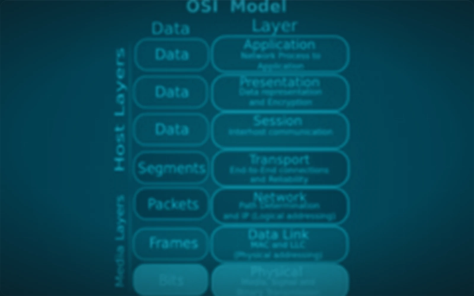
The Open Systems Interconnection (OSI) model is a seven-layer reference framework for how devices communicate across a network. It is a conceptual model rather than an implementation: nothing on your machine is "the session layer", and its value is as shared vocabulary.
| Layer | Name | Responsibility | Examples |
|---|---|---|---|
| 7 | Application | Network services used directly by applications | HTTP, DNS, FTP, SMTP, SSH |
| 6 | Presentation | Formatting, encoding, encryption, compression | TLS, JSON, XML, character encodings |
| 5 | Session | Establishing, managing and ending sessions | Session setup and teardown |
| 4 | Transport | End-to-end delivery between applications | TCP, UDP |
| 3 | Network | Logical addressing and routing between networks | IP, ICMP, routers |
| 2 | Data link | Node-to-node delivery on one link, framing, error detection | Ethernet, Wi-Fi (802.11), MAC addresses, switches |
| 1 | Physical | Transmission of raw bits over a medium | Cables, fibre, radio, hubs |
Two mnemonics that people actually use, because the order matters more than the descriptions:
- Layer 7 down to layer 1: All People Seem To Need Data Processing.
- Layer 1 up to layer 7: Please Do Not Throw Sausage Pizza Away.
Layer 1: the physical layer
The physical layer transmits raw bits over a medium. It defines voltages, light pulses, radio signalling, connector shapes and pin assignments, and it has no idea what any bit means.
Cables, fibre, radio and hubs live here. A hub is a layer 1 device in the strictest sense: it repeats an incoming signal to every other port without reading anything.
Layer 2: the data link layer
The data link layer delivers data between two devices on the same link. It wraps data into frames, addresses them with media access control (MAC) addresses, and detects frames that arrived corrupted.
Ethernet and Wi-Fi are layer 2. So is a switch, which reads the destination MAC address of a frame and sends it out one port. The key limit of this layer is its reach: a MAC address identifies an interface on one local link and is rewritten at every router, so nothing at layer 2 can address a machine on another network.
Layer 3: the network layer
The network layer addresses devices logically and routes packets between separate networks. It is where an IP address lives, and where a router decides which way to send a packet next.
This is the layer that makes an internet possible.
Layer 2 gets a frame across one link; layer 3 gets a packet across an arbitrary chain of them, without either end knowing what those links are made of.
The Internet Control Message Protocol (ICMP), which ping uses, is also layer 3.
Layer 4: the transport layer
The transport layer provides end-to-end communication between applications rather than between machines. It adds port numbers, which is what lets one machine run a web server and a mail server at once, and it can add reliability on top of a network layer that offers none.
Two protocols dominate:
- TCP (Transmission Control Protocol) numbers what it sends, acknowledges what it receives, retransmits what is lost and delivers the result in order.
- UDP (User Datagram Protocol) sends datagrams and stops there. No ordering, no retransmission, far less delay.
Neither is better. TCP is right for a file that must arrive intact; UDP is right for a voice call, where a packet that arrives late is worse than one that never arrives.
Layers 5, 6 and 7: session, presentation and application
The top three are grouped here because in practice they arrive as one thing.
The session layer establishes, manages and ends conversations between applications. The presentation layer translates, formats, encrypts and compresses so that two different systems agree what the bytes mean; Transport Layer Security (TLS) and character encoding are usually put here. The application layer is the one applications speak directly: HTTP, DNS, the File Transfer Protocol (FTP), the Simple Mail Transfer Protocol (SMTP) and Secure Shell (SSH).
Real protocol stacks do not draw firm lines between these three, which is exactly why the TCP/IP model does not either.
The TCP/IP model, and how it maps onto OSI
The TCP/IP model describes the protocol suite the internet actually runs on, in four layers rather than seven.
| Layer | Name | Responsibility | Examples | OSI equivalent |
|---|---|---|---|---|
| 4 | Application | Services applications use | HTTP, DNS, SSH, FTP | 7, 6, 5 |
| 3 | Transport | End-to-end delivery, ports, reliability | TCP, UDP | 4 |
| 2 | Internet | Logical addressing and routing | IP, ICMP | 3 |
| 1 | Network access | Delivery across one physical network | Ethernet, Wi-Fi, ARP | 2, 1 |
One protocol in that bottom row is worth naming now: the Address Resolution Protocol (ARP) sits at the boundary between addressing and delivery, and it gets a post of its own at the end of this series.
The difference is not a disagreement about how networks work. OSI was designed as a complete reference and then reality was built next to it; TCP/IP was built first and described afterwards, so it collapses the layers nobody implemented separately.
Use OSI's numbers when talking to people, because "a layer 3 problem" and "a layer 7 rule" are understood everywhere. Use TCP/IP's structure when reasoning about what is actually running.
Encapsulation: how data becomes a frame
Encapsulation is the process of adding each layer's own control information to the data as it travels down the stack on the sending device. Every layer wraps what it received from the layer above and hands the result down.
| Layer | What the unit is called here | What this layer adds |
|---|---|---|
| Application | Data | The application's own headers, such as an HTTP request line |
| Transport | Segment (TCP) or datagram (UDP) | Source and destination port numbers |
| Network | Packet | Source and destination IP addresses, and a time to live |
| Data link | Frame | Source and destination MAC addresses, and a frame check sequence |
| Physical | Bits | Nothing. It signals what it was handed |
The names matter because people use them precisely. "Packet" and "frame" are not synonyms: a frame is a packet with layer 2 addressing wrapped around it, and the frame is discarded and rebuilt at every hop while the packet crosses the whole path.
Decapsulation: the same trip in reverse
Decapsulation is the reverse, on the receiving device. Each layer removes the header its counterpart added, acts on it, and hands what is left to the layer above.
The data link layer checks the frame arrived intact and strips the MAC addresses. The network layer confirms the destination address is its own and strips the IP header. The transport layer reads the port number and hands the payload to whichever application is listening on it.
| Encapsulation | Decapsulation | |
|---|---|---|
| Happens at | The sender | The receiver |
| Direction through the stack | Downwards, application to physical | Upwards, physical to application |
| Headers | Added | Read, then removed |
Seeing the top of the stack
Everything below the application layer is invisible without packet capture, which needs privileges most people running a command do not have. The top of it does not.
curl -sI https://example.com
HTTP/2 200
date: Sat, 05 Sep 2026 11:02:35 GMT
content-type: text/html
server: cloudflare
last-modified: Wed, 02 Sep 2026 22:14:26 GMT
allow: GET, HEAD
accept-ranges: bytes
age: 7078
cf-cache-status: HIT
cf-ray: a364be197f778420-LHE
That is layer 7, and it is the only part of the exchange the command prints. Underneath it, unshown: a TLS session at layer 6, a TCP connection to port 443 at layer 4, packets carrying IP addresses at layer 3, and a frame per hop at layer 2, each of which was built, sent, stripped and rebuilt to produce those ten lines.
The HTTP/2 on the first line is worth noticing.
The protocol version is an application-layer detail, and nothing below layer 4 knew or cared which version was in use.
Using the models to locate a fault
Neither model is a description of a real program, and treating either as one causes more confusion than it resolves. What they are good for is locating a problem.
A machine that cannot reach anything, including its own gateway, is failing at layer 1 or 2. A machine that reaches its gateway and nothing beyond is failing at layer 3. A machine that reaches the server but is refused on one port is at layer 4. A machine that connects and gets an error page is at layer 7.
Four questions in order, and each one eliminates everything below it. That is the entire practical value of the model, and it is a large one.
What comes next in this series
The next post covers the physical layer in detail: copper against fibre, the Cat cabling standards, the connectors and transceiver modules on the ends of them, link speed, and Power over Ethernet.
These posts follow my own notes as I work through the material, so they go in the order the topics are learned rather than the order they would be taught in a reference.