Two networks can use the same cable, the same switch and the same protocol and still behave completely differently when something breaks. What separates them is the shape: which device is connected to which, and how many paths exist between any two of them.
That shape is the topology, and it is the second post in a series working through networking from the bottom. The first covered what a network is and what bandwidth, throughput, latency and jitter each measure.
What a topology is
A network topology is the arrangement of the links between devices. It answers one question: to get from A to B, what does the data have to pass through?
There are two of them and they are not always the same. The physical topology is where the cables actually run. The logical topology is the path the data takes, which the physical wiring does not have to match. Classic Ethernet is the standard example: it was wired as a star into a hub, and behaved as a bus, because the hub repeated every signal to every port.
Everything below is the physical arrangement unless it says otherwise.
The topologies compared
| Topology | How it is wired | Paths between two devices | Where you meet it |
|---|---|---|---|
| Bus | Every device taps one shared backbone cable | One | Early Ethernet, now obsolete |
| Star | Every device has its own link to a central device | One, through the centre | Every modern office and home network |
| Ring | Each device links to exactly two neighbours, closing a loop | Two, one each way round | Metropolitan fibre rings, older token networks |
| Mesh | Devices link to many or all of the others | Many | Internet backbones, wireless mesh, military links |
| Tree | Stars connected into a hierarchy | One, through the branch above | Campus and multi-floor networks |
| Hybrid | Two or more of the above joined together | Depends on the join | Almost every real network of any size |
| Point-to-point | One dedicated link between exactly two devices | One | Leased lines, switch uplinks, radio links |
Bus topology
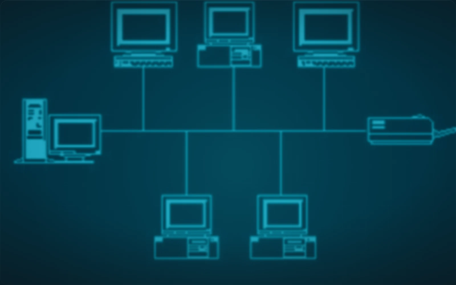
A bus topology connects every device to a single shared cable, called the backbone. A signal put on the backbone by one device travels along it and reaches all the others.
Only one device can transmit usefully at a time. When two transmit at once the signals overlap on the shared wire and both are lost, which is a collision, and the whole shared segment is one collision domain.
The backbone is also a single point of failure along its whole length: a break anywhere splits the network in two. This is why bus is a historical topology rather than a design choice.
Star topology
A star topology connects every device by its own cable to one central device, normally a switch. All traffic between two devices passes through the centre.
This is what almost every network you will touch actually is. It wins for a reason that has nothing to do with elegance: a cable fault takes out one device instead of the network, and a device can be added or removed without disturbing anything else.
The cost is the obvious one. The central device is a single point of failure for everything attached to it, which is why real networks give it redundant power, redundant uplinks, or a second switch.
Ring topology
A ring topology connects each device to exactly two neighbours, so the links close into a loop. Data travels around the ring from device to device until it reaches its destination.
Because the loop closes, there are two paths between any two devices, one in each direction. That is the appeal: a ring can be built to survive a single break by sending everything the other way round, which is why fibre rings are common across a city.
A plain ring with no such protection has the opposite property, and one break stops it.
Mesh topology
A mesh topology connects devices to many of the others, and in a full mesh every device has a direct link to every other one.
It is the most resilient arrangement and the most expensive.
A full mesh of n devices needs n(n-1)/2 links, so ten devices need forty-five cables and twenty need one hundred and ninety.
That growth is why full mesh is reserved for places where a link failure is not survivable, and why real deployments are usually a partial mesh instead.
The internet's backbone is a partial mesh, which is the reason a cut cable reroutes rather than disconnects a continent.
Tree topology
A tree topology arranges stars into a hierarchy: a device at the top, branches below it, devices at the leaves. It combines the star's per-device wiring with a backbone connecting the branches.
This is how a building is wired in practice. One switch per floor, each connected up to a distribution switch, that connected up to the core. The failure behaviour follows the hierarchy: losing a leaf costs one device, and losing a branch costs everything under it.
Hybrid topology
A hybrid topology is two or more different topologies joined into one network, and it is what a real network of any size actually is.
A campus is stars inside buildings, a ring or a partial mesh between them, and point-to-point links out to the provider. Naming the whole thing is not useful. Naming the topology of the part you are looking at is.
Point-to-point and point-to-multipoint
A point-to-point topology is a single dedicated link between exactly two devices, with nothing shared and nothing in between. A switch-to-switch uplink, a leased circuit between two offices, and a microwave link across a valley are all point-to-point.
A point-to-multipoint topology has one central device communicating with several others over a shared medium. A Wi-Fi access point serving the laptops in a room is the everyday example: one radio at the centre, many clients, one shared channel between them.
Client-server and peer-to-peer architecture
Topology is the wiring. Architecture is which device asks and which device answers, and the two are independent: the same star network runs either.
In a client-server architecture, clients send requests to a central server, and the server does the work and replies. A browser asking a web server for a page is the canonical case. Everything is in one place, which makes it easy to secure, easy to back up, and a single point of failure.
In a peer-to-peer (P2P) architecture, devices talk directly to one another and each is both client and server. A file-sharing peer downloads a piece of a file from one machine while uploading another piece to a second. There is no centre to lose, and equally no centre to control, log or patch.
What a single link failure does in each
This is the question the topology answers, and the reason it is worth naming before you troubleshoot anything.
| Topology | One link fails | The central device fails |
|---|---|---|
| Bus | The backbone splits and the segment stops | No central device |
| Star | One device is isolated | Everything attached stops |
| Ring, unprotected | The loop opens and the ring stops | No central device |
| Ring, protected | Traffic reverses direction and continues | No central device |
| Full mesh | Traffic takes another of the many paths | No central device |
| Tree | Everything below the failed link is isolated | Everything below it stops |
Read the shape before reading the symptom. "Three machines on one floor lost the network at the same moment" is a sentence about a tree, and it names the branch above them without anybody having to test a single cable.
You can see the shape of your own connection with one command:
ip route get 8.8.8.8
8.8.8.8 via 192.168.0.1 dev wlp0s20f3 src 192.168.0.12 uid 1000
    cache
via 192.168.0.1 is the centre of the star this machine sits in.
Every packet it sends to anything outside the local network goes through that one device first, so whatever else is on this network, that address is the thing to check when nothing works.
What comes next in this series
The next post covers the Open Systems Interconnection (OSI) model and the TCP/IP model, the layered maps that everything else in this series is drawn on, and how a piece of data becomes a frame on the wire.
These posts follow my own notes as I work through the material, so they go in the order the topics are learned rather than the order they would be taught in a reference.