A virtual local area network (VLAN) divides one physical switched network into several separate layer 2 networks, and the Spanning Tree Protocol (STP) keeps a switched network with redundant links from forwarding frames around a loop forever. With Spanning Tree turned off, one broadcast frame sent into two lab bridges joined by two links was forwarded across one of those links 190,814 times in one second.
The two are usually taught apart and almost always deployed together: VLANs decide which devices share a broadcast domain, and Spanning Tree decides which of the links between switches may carry it. Both work on the Ethernet frame described in Ethernet frames and switching.
What a VLAN is
A VLAN is a separate layer 2 broadcast domain carved out of shared switching hardware, so devices in different VLANs are in different broadcast domains even when they are plugged into the same switch.
Nothing sent in one VLAN reaches another. For two devices in different VLANs to communicate at all, the traffic must be routed at layer 3, where a firewall or an access control list can decide whether it is allowed.
VLANs are used for four things:
- Segmentation. Employees, guests, servers, voice and cameras on separate networks regardless of where they physically sit.
- Broadcast control. A broadcast reaches only its own VLAN, so a large site does not have one enormous broadcast domain.
- Security. Layer 2 isolation by default, with all traffic between VLANs forced through a routed hop that can be filtered and logged.
- Organisation. Grouping by function rather than by floor, so moving a desk does not mean re-cabling.
A VLAN is not a security control on its own. It puts traffic through a place where a control can be applied, which is a different and much weaker claim than isolation.
Access ports and trunk ports
A switch port is either an access port or a trunk port, and the kind decides whether frames on it carry VLAN information.
An access port belongs to a single VLAN and connects an end device: a computer, a printer, a camera. The device sends and receives ordinary untagged frames and has no idea a VLAN exists, but the switch knows, because the port is configured with a VLAN, and it applies that VLAN to everything arriving there.
A trunk port carries traffic for several VLANs over one physical link. It connects infrastructure to infrastructure: switch to switch, switch to router, switch to firewall, switch to hypervisor.
That raises a problem. If frames from several VLANs share one cable, the switch at the far end needs some way to tell which frame belongs to which VLAN, and an ordinary Ethernet frame has nowhere to put that.
802.1Q tagging
IEEE 802.1Q, the Institute of Electrical and Electronics Engineers (IEEE) standard for VLANs, solves it by inserting a 4-byte tag into the Ethernet frame, after the source media access control (MAC) address and before the field that says what the payload is.
An ordinary frame:
| Destination MAC | Source MAC | EtherType | Payload | Frame check sequence |
|---|
A tagged frame:
| Destination MAC | Source MAC | 802.1Q tag | EtherType | Payload | Frame check sequence |
|---|
The sequence across a trunk, end to end:
- A computer on an access port in VLAN 10 sends an ordinary untagged frame.
- The switch knows the port belongs to VLAN 10.
- Sending the frame over a trunk, the switch inserts an 802.1Q tag carrying VLAN 10.
- The switch at the other end reads the tag and knows which VLAN the frame belongs to.
- Delivering the frame to an access port, that switch removes the tag before sending it on.
The end devices never see a tag. Tagging exists only on the links between switches, which is why plugging a laptop into a trunk port usually produces nothing useful.
Linux can put a tag on a frame itself, which is how the lab for this post builds two VLANs on one link: one VLAN interface per VLAN on each end of the same cable, each with its own address range.
ip link add link lab0 name lab0.10 type vlan id 10
ip link add link lab0 name lab0.20 type vlan id 20
A ping in VLAN 10 and another in VLAN 20 then cross the same link, and every frame on it carries a tag.
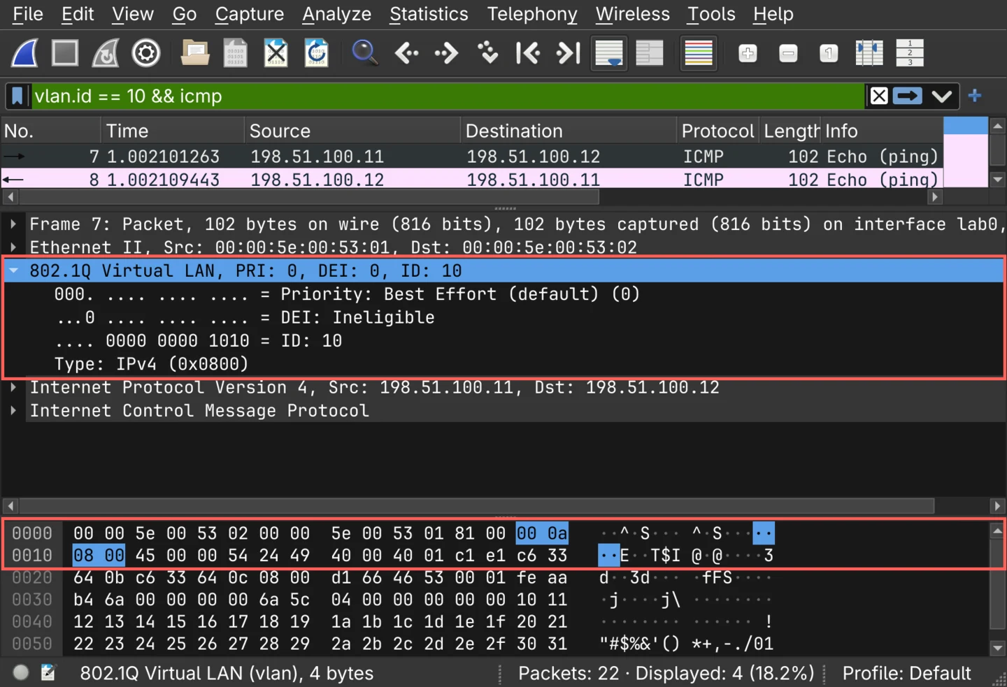
The hex dump shows how a receiver knows a tag is there at all.
Offset 12 is where an ordinary frame's EtherType sits, and in this frame it holds 81 00.
That value is the tag's first half, and the frame's real EtherType, 08 00 for IPv4, has moved four bytes along to follow the tag.
Inside the 802.1Q tag
The 4-byte tag has two halves: a 2-byte marker, and 2 bytes of control information.
| Part | Size | What it does |
|---|---|---|
| Tag protocol identifier (TPID) | 16 bits | Always 0x8100, which marks the frame as carrying an 802.1Q tag |
| Priority code point (PCP) | 3 bits | Traffic priority, for layer 2 quality of service |
| Drop eligible indicator (DEI) | 1 bit | Marks the frame as droppable first under congestion |
| VLAN identifier (VID) | 12 bits | Which VLAN the frame belongs to |
The last three together are the tag control information (TCI), which in the capture above is 00 0a: priority 0, drop eligible 0, and VLAN 10.
The VLAN identifier (VID) is 12 bits, so its range is 0 to 4095. Not all of it is usable: 0 means "no VLAN, priority only", 4095 is reserved, and 1 is the default VLAN every port starts in. That leaves 4094 usable VLANs, and that ceiling is one of the limits RFC 7348 gives for designing Virtual Extensible Local Area Network (VXLAN), which carries a 24-bit identifier instead.
Why redundant switch links create loops
A single link between two switches is a single point of failure, so real networks add a second one. At layer 3 that would be fine. At layer 2 it is not, and the reason is a field that one header has and the other does not.
An IP packet carries a time to live that decreases at each router, so a packet caught in a routing loop eventually dies. An Ethernet frame has no such field. There is no hop count at layer 2 and nothing that expires.
So a broadcast that enters a loop is flooded by the first switch, received by the second, flooded back, received by the first, and goes round again, for as long as the loop exists.
In the lab, two Linux bridges, brA and brB, are joined by two links, with Spanning Tree off. A host on a third port of brA sends exactly one broadcast frame, and after one second one of the two links is taken down to break the loop.
./lab.sh loop
All three symptoms of a switching loop are in those numbers:
- A broadcast storm. One frame became 190,814 frames sent by one bridge across one link, in one second, with nothing in any of them to stop it.
- Duplicate frames. The host that sent the frame received it back 381,626 times.
- MAC address table instability. The sender is attached to brA's third port, but its frames kept arriving back on the looped ports too, and brA's last entry for it points at
lab0, a link to the other bridge. A frame addressed to that host would be sent the wrong way.
The loop stopped only because a link was taken down. On a network with no Spanning Tree that link would stay up.
What the Spanning Tree Protocol does
The Spanning Tree Protocol (STP) is a layer 2 protocol that finds the loops in a switched network and blocks enough ports to remove them, while keeping those links physically connected and ready to take over.
The result is a network that is physically redundant and logically loop-free. Every switch is reachable, exactly one active path exists between any two of them, and a blocked link comes back when an active one fails.
Switches build this picture by exchanging bridge protocol data unit (BPDU) frames, which are sent every 2 seconds by default and carry what each switch needs to work out its place in the topology, notice a change and recalculate.
Electing the root bridge
The first thing the protocol does is agree on a reference point: one switch becomes the root bridge, and every path is measured towards it.
The election is by lowest bridge identifier, which is a bridge priority followed by the switch's MAC address. Priority is compared first, and the MAC address is the tiebreaker when priorities are equal.
The default priority is 32768 on every switch, which means that out of the box the root bridge is whichever switch happens to have the lowest MAC address. That is an accident of manufacturing rather than a design decision, which is why the switch that should be root is given a lower priority on purpose.
The lab sets up both cases on its two bridges: brA keeps the default, and brB is given 4096 when it is created.
ip link add brA type bridge stp_state 1 priority 32768
ip link add brB type bridge stp_state 1 priority 4096
Each bridge starts by claiming to be root, and in the capture brA's claim goes out first, with its own 32768 as the root priority. brB's claim follows, and it is the one that wins.
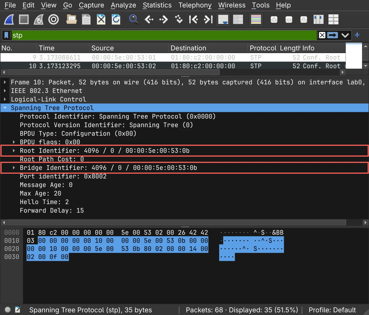
A BPDU whose root identifier and bridge identifier are the same comes from the root bridge itself. Its root path cost is 0 for the same reason: it is already where every other switch is measuring towards. The timers below it, 20 seconds of maximum age, 2 seconds between hellos and 15 seconds of forward delay, are the 802.1D defaults, and they set how long every change of state below takes.
Spanning Tree port roles
Once a root is elected, each port takes a role.
| Role | Where it is | What it does |
|---|---|---|
| Root port | On every non-root switch, one per switch | The port with the best path towards the root bridge. Forwards |
| Designated port | One per network segment | The forwarding port for that segment, closest to the root |
| Blocking, alternate or backup | The remaining redundant ports | Does not forward normal traffic, still listens for BPDUs |
The root bridge itself has no root port, because every one of its ports is designated.
A blocked port is not disabled. The cable is connected, the link is up, and the port keeps receiving BPDUs. The capture above was taken on brA's blocked port, and BPDUs from brB kept arriving on it every 2 seconds for the whole time it was blocked; what a blocked port does not do is forward user traffic, and that is what breaks the loop.
Spanning Tree port states
Classic 802.1D moves a port through four states before it carries traffic:
| State | Learns MAC addresses | Forwards traffic | Purpose |
|---|---|---|---|
| Blocking | No | No | Receives BPDUs only |
| Listening | No | No | Works out the topology |
| Learning | Yes | No | Builds the MAC address table before forwarding |
| Forwarding | Yes | Yes | Normal operation |
There is also a disabled state, for a port that is administratively down.
The sequence exists to avoid forwarding into a topology that has not settled, and it is slow. Listening and learning each last one forward delay, 15 seconds by default, so a port that comes up takes about 30 seconds to pass traffic. When a switch learns of a failure only because BPDUs stop arriving, it first waits out the 20-second maximum age, which brings the total to about 50 seconds.
Rapid Spanning Tree Protocol (RSTP), standardised as 802.1w, replaced those timers with a proposal and agreement handshake between neighbouring switches, so a port can move to forwarding without waiting them out. The 2004 revision of 802.1D folded RSTP in and retired the original protocol, and the classic state list is worth knowing mainly because its vocabulary survived into what replaced it.
What happens when a link fails
The lab's two bridges run classic 802.1D with its default timers.
brB is root, brA's port on the second link (lab2) is its root port, and its port on the lab link (lab0) is blocked.
Then lab2 is taken down.
./lab.sh stp
The designated_root of 1000.0:0:5e:0:53:b is brB: 1000 is 4096 in hexadecimal, followed by brB's MAC address.
brA sees its own link go down, so it does not wait for BPDUs to time out: lab0 leaves blocking at once.
It then spends one forward delay listening and one learning, and at 33 seconds the link that had carried nothing since the lab started is forwarding.
The redundancy was there all along. Spanning Tree's whole contribution is keeping that second link from looping the network on a normal day, and bringing it into service when the first one goes.